
My oblong loop antenna (loop 5 meters wide, 2 meters high) works surprisingly well on the higher shortwave bands, and it also works well on receiving the lower bands, and the SWR there is to high to tune it with a tuner at the transceiver. That is why I build a tuner for it, directly at the antenna.
Purpose: coarse tuning of the antenna, with a simple and easy to build circuit at the antenna, to reduce cable losses, fine tuning at the transceiver.
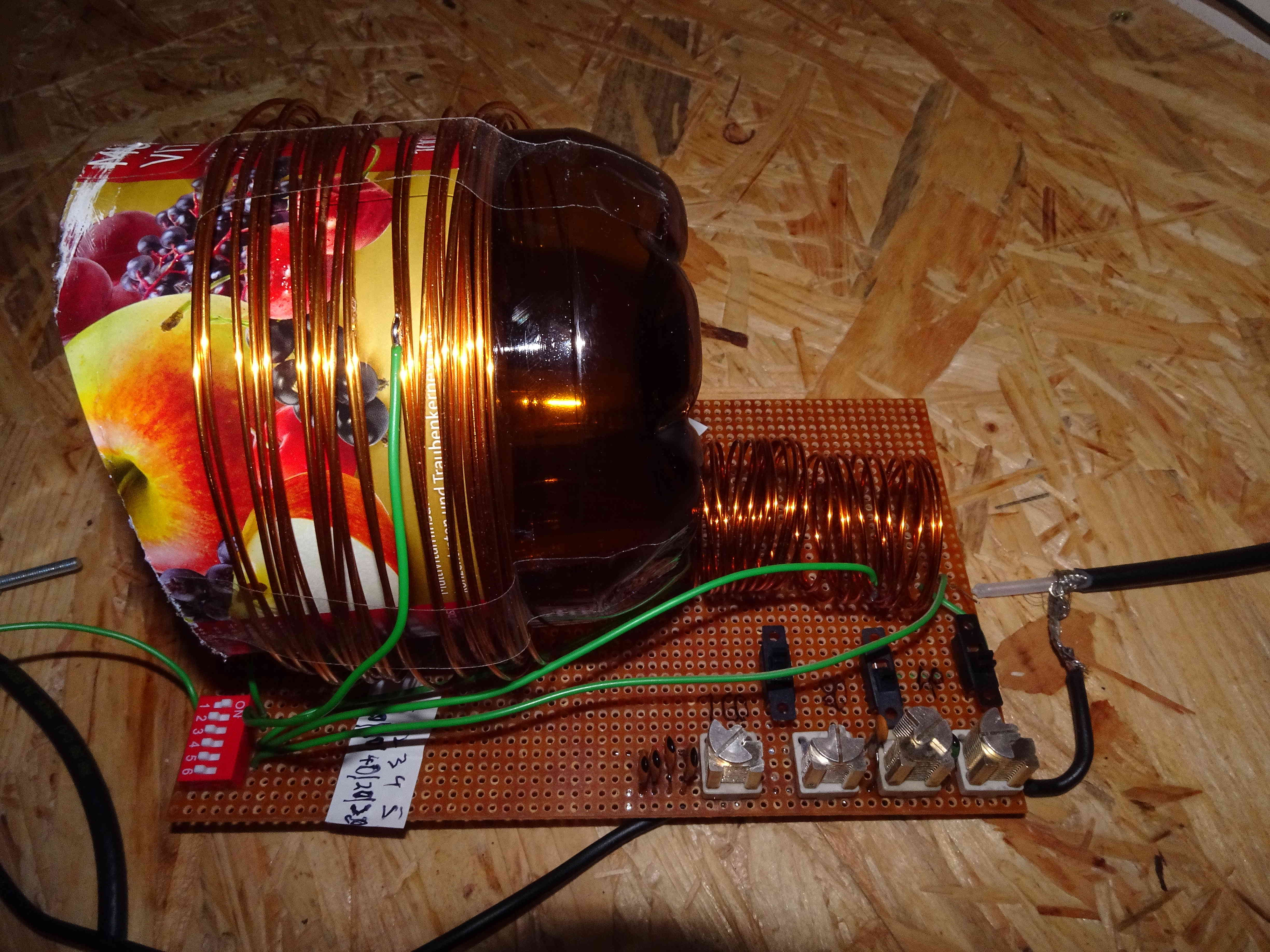
You can see the resulting schematic in the picture, and the finished board in the photo. It is a classical L-match circuit, and contains several switches to select the band, hence accessibility is needed, and it contains adjustable capacitors for coarse tuning. For different antenna dimensions the values of the inductors and capacitors have to be adjusted. I used my MFJ antenna analyzer to measure the loops impedance on the different bands and to compute the values for the capacitances and inductances for a roughly 50 Ohm match. There are 2 banks of switches: One to select the inductor (the tap for the coil), and one bank to select the capacitor, as seen in the schematic. On the board I marked the switches with the band name with permanent ink.
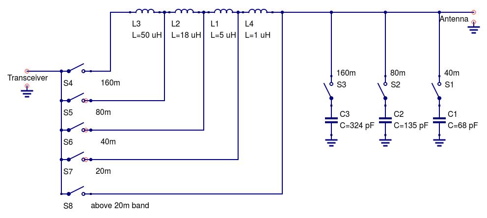 Schematic
I found important:
Use only ceramic capacitors, other capacitors become hot and change their capacitances and spoil the matching this way, and loose valuable RF energy. Even small size ceramic capacitors are possible, in my case I can use 100W of power with capacitors about 5mm in diameter.
Use adjustable capacitors in parallel to the fixed ceramic capacitor for the coarse tuning (down to about SWR=5 or lower, because then the cable losses are sufficiently low). In my case I used 40 pF adjustable capacitors.
Only use air coils for inductances, coil carriers with metal or too small toroid cores become warm or hot, potentially spoil the matching and distort the signal, and loose energy. In my case I used 3 inductors, 2 of them with 3cm diameter and 2cm lenghts and 10 windings of 1mm diameter insulated Cu wire, so each has about 3uH inductance (see also: http://www.qsl.net/in3otd/indcalc.html). The first coil from the antenna has a tap after 5 windings (for about 1 uH) for the 20m band. My last inductor has 10 cm diameter, 24 Windings and 4cm lengths (for a total of about 68uH), and it has a tab for 80m after 10 windings seen from the other inductors (for about 18uH).
Use a Choke Balun: I use a choke balun with 11 turns of the coax cable at 20cm diameter. Omitting the balun makes the cable shielding act like a considerable lossy capacitance, which de-tunes the tuner and leads to lossesl
My experience with it: I find that I can tune my oblong loop antenna indeed to SWR<5, such that fine tuning can be done with an internal antenna tuner or a tuner at the transceiver. I compared the loop antenna with my (tuned) 9m vertical antenna: on the 40m band the loop has an about 1 step lower signal, on 80m both are comparable, on 160m the vertical seem to be slightly better. I found it fun using it, it is a relatively simple antenna, and using this antenna tuner, I can now use it and had contacts on all SW bands, including down to the 160m band, and it works fine up to about 100W, despite the small elements.